 |
DACT
|
 |
|
|
|
|
DACT stepped audio attenuators. Danish Audio ConnecT manufactures a range of High-End stepped audio attenuators for Hi-Fi, A/V and Pro-Audio, used by DIY Audiophiles and audio equipment manufacturers throughout the world: Both models CT1 and CT2 use a resistor network built on non-inductive SMD resistors. The SMD resistors are mounted on a very compact PCB, offering a very short and ‘pure’ signal path. All switch contacts and connectors are gold plated.
|
|
|
 |
|
|
|
|
 |
|
|
|
|
 |
 |
 |
 |
 |
 |
 |
 |
 |
 |
 |
 |
 |
 |
 |
 |
 |
 |
 |
 |
 |
 |
 |
 |
 |
 |
 |
 |
 |
 |
 |
 |
 |
 |
 |
 |
 |
 |
 |
|
 |
|
|
|
The CT2 Audio Volume Controls are high quality stepped 24-position attenuators. Designed for maximum sonic quality, accuracy and reliability. This makes them equally suited for audiophile and professional applications.
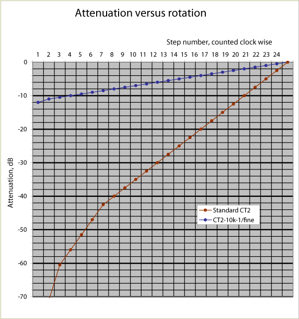
Available as master volume control with 60dB attenuation range (1, 2, 4, 6, 8 decks) and as individual channel fine adjustment (CT2-10k-1/fine) with 0.5dB level change between each step (only available with 1 deck)
Their series resistor networks consist of 23 non-inductive, low noise, SMD metal film resistors.
The layout of the PC Boards and the choice of SMD resistors have reduced the signal path to a minimum length (typical five times shorter than conventional stepped attenuator designs with leaded resistors). The PCB design combined with the special resistors also account for the very low series inductance and the very low stray capacitance.
The result is a bandwidth beyond even the most demanding audiophiles’ requirements.
There has been special care taken to ensure the durability of CT2. Therefore, all contacts and PCB traces are gold plated to prevent any corrosion. As a result, the CT2s will maintain their specifications after long time of use even in hot and humid environments.
|
|
|
|
FEATURES
|
|
SCHEMATIC
|
|
|
|
- Low noise, non-inductive, metal film SMD resistor network
- Compact design
- Entire signal path gold plated
- Shorter signal path than conventional attenuators with leaded resistors
- Reduced inductance and stray capacitance
- Improved sonic quality
- Improved accuracy - 0.05dB tracking and 0.05dB attenuation accuracy
- Improved reliability
- Increased bandwidth
- Reduced distortion, less than 0.0001%
|
|
|
|
 |
|
|
|
|
|
|
SPECIFICATIONS
|
|
MAXIMUM RATINGS
|
|
Note
|
Parameter
|
Conditions/comments
|
Value
|
Unit
|
|
1
|
Switching capacity
|
(resistive load)
|
2V/2A
24V/0.6A
42V/0.4A
|
AC/DC
|
|
1
|
Power dissipation
|
(each resistor)
|
100
|
mW
|
|
1
|
Operating ambient temp. range
|
|
-25 to +70
(-13 to +158)
|
deg. C
(deg. F)
|
|
1
|
Storage temperature range
|
|
-40 to +85
(-40 to 185)
|
deg. C
(deg. F)
|
|
|
|
|
|
|
|
MECHANICAL CHARACTERISTICS
|
|
Note
|
Parameter
|
Conditions/comments
|
Value
|
Unit
|
|
|
Number of positions
|
|
24
|
|
|
|
Indexing angle
|
|
15
|
deg.
|
|
|
Switching function
|
|
shorting
|
|
|
|
Gold plating, contacts
|
(hard-gold)
|
3
|
μm
|
|
|
Gold plating, wiper
|
(hard-gold)
|
8
|
μm
|
|
2
|
Mechanical life
|
|
>25,000
|
cycles
|
|
|
Switching torque
|
1-, 2-, and 4-decks versions
6- and 8-decks versions
|
1.5
3.5
|
Ncm
Ncm
|
|
|
Nut tightening torque
|
|
max. 300
|
Ncm
|
|
|
|
|
|
|
|
DC ELECTRICAL CHARACTERISTICS
|
|
Note
|
Parameter
|
Conditions/comments
|
Value
|
Unit
|
|
|
Total resistance range
|
(standard versions of CT2)
|
10, 20, 50,
100, 250, 500
|
kOhm
|
|
|
|
(fine-adjustment version)
|
10
|
kOhm
|
|
3
|
Total resistance accuracy
|
(new)
|
0.1
|
%
|
|
|
Attenuation steps, standard version
|
(source output impedance = 0),
(load input impedance = infinite)
|
0, 2, 4, 6, 8, 10, 12, 14,
16, 18, 20, 22, 24, 26,
28, 30, 32, 34, 38, 42,
46, 50, 60, infinite
|
dB
|
|
|
Attenuation steps, version for fine- adjustment
|
(source output impedance = 0),
(load input impedance = infinite)
|
0, 0.5, 1, 1.5, 2, 2.5, 3,
3.5, 4, 4.5, 5, 5.5, 6, 6.5,
7, 7.5, 8, 8.5, 9, 9.5,
10, 10.5, 11, 12, infinite
|
dB
|
|
3
|
Attenuation accuracy
|
(new)
|
+/- 0.05
|
dB
|
|
3
|
Matching accuracy (tracking)
|
(between two decks)
|
+/- 0.05
|
dB
|
|
4
|
Contact resistance
|
(new)
|
max. 0.01
|
Ohm
|
|
|
Contact capacitance
|
(adjacent contacts)
|
1
|
pF
|
|
|
Series inductance
|
(10 kOhm, input to ground)
|
max. 0.4
|
μH
|
|
|
|
AC ELECTRICAL CHARACTERISTICS
|
|
Note
|
Parameter
|
Conditions/comments
|
Value
|
Unit
|
|
4
|
-3dB bandwidth
|
(10k, A = -6dB)
|
50
|
MHz
|
|
5
|
Noise voltage
|
(10k, input to ground pin)
|
12.8
|
nV/Hz
|
|
6
|
Total harmonic distortion
|
(A = -6dB, fo = 1kHz)
|
max. 0.0001
|
%
|
|
|
|
Notes
|
|
1
|
Exposure to maximum rating conditions for extended periods of time may affect device reliability
|
|
2
|
One cycle is defined as a full rotation from one end stop to the other and return
|
|
3
|
Typical values at +25 deg. C ambient temperature. Output (pin 2) unloaded
|
|
4
|
Measuring probe input capacitance 1 pF
|
|
5
|
Theoretical value for an ideal 10k resistor
|
|
6
|
Measured with Panasonic Audio Analyzer VP-7722P
|
|
|
|
To the top 
|
|
|
|
 |
|
|
|
To the top 
|
|
|
OUTLINE DRAWING
|
|
|
|
|
|
|
 |
|
|
|
To the top 
|
|
|
|
|
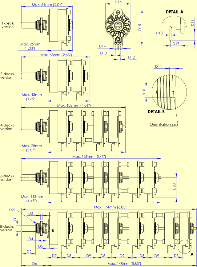
NOMINAL DIMENSIONS
Dimensions common for all models
|
|
Dim.
|
Description
|
Number
|
|
D1
|
Shaft diameter
|
6.0mm
(0.236”)
|
|
D2
|
Shaft length
|
14.5mm
(0.57”)
|
|
D3
|
Nut thickness
|
2.5mm
(0.10”)
|
|
D4
|
Thread length
|
9.5mm
(0.37”)
|
|
D5
|
Distance
|
2.5mm
(0.10”)
|
|
D6
|
Distance
|
25mm
(0.98”)
|
|
D7
|
Distance to terminals
|
13.2mm
(0.52”)
|
|
D8
|
Distance 1 between terminals
|
14.7mm
(0.58”)
|
|
D9
|
Distance 2 between terminals
|
20.2mm
(0.80”)
|
|
D10
|
Orientation pin width
|
2.5mm
(0.10”)
|
|
D11
|
Orientation pin height
|
1.3mm
(0.05”)
|
|
D12
|
Distance between terminal pins
|
2.54mm
(0.1”)
|
|
D13
|
Terminal pin width
|
0.64mm
(0.025”)
|
|
D14
|
PCB bottom width
|
8.7mm
(0.34”)
|
|
D15
|
Total height when mounted in PCB
|
36.5mm
(1.44”)
|
|
D16
|
Maximum width
|
25mm
(0.98”)
|
|
D17
|
Terminal distance to PCB
|
6.0mm
(0.24”)
|
|
D18
|
Terminal pin thickness
|
0.64mm
(0.025”)
|
|
D19
|
Terminal pin length below PCB
|
3.5mm
(0.14”)
|
|
D20
|
Distance from PCB bottom to shaft center
|
19.9mm
(0.783”)
|
|
D21
|
Thread type
|
M10 x 0.75
|
|
|
|
|

|
|
|
|
|
|
CONNECTIONS
|
|
|
|
|
|
 |
|
|
|
|
|
To the top 
|
|
|
|
ORDERING INFORMATION
|
|
Part number
|
Description
|
|
CT2-10k-1/fine
|
1-channel stepped attenuator, fine adjustment (0.5dB steps)
|
|
CT2-xxxk-1
|
1-channel stepped audio attenuate (mono)
|
|
CT2-xxxk-2
|
2-channel stepped audio attenuate (stereo)
|
|
CT2-xxxk-4
|
4-channel stepped audio attenuate (balanced stereo)
|
|
CT2-xxxk-6
|
6-channel stepped audio attenuate (AV audio)
|
|
CT2-xxxk-8
|
8-channel stepped audio attenuate (AV audio)
|
|
xxx refers to the attenuator resistance. Available resistances are 010 (10kOhm), 020 (20kOhm), 050 (50kOhm), 100kOhm, 250kOhm, 500kOhm
|
|
|
|
|
|
|
|
|
 To the top To the top
|
|
|
 |
 |
 |
|
|
|
|